Cookies sur les sites Web Omega
Nous utilisons des cookies sur ce site Web. Ces cookies sont indispensables au bon fonctionnement de notre site.
Si vous continuez sans modifier vos paramètres, nous supposerons que vous êtes heureux de recevoir tous les cookies de notre site Web.
Pour de plus amples informations à ce sujet, veuillez cliquer ici
Fermer
Panier  |  Contact  | 
NUMÉRO VERT 0805 541 038
INTERNATIONAL+33 01 57 32 48 17
Layer N Banner

High Accuracy Pitot Tubes for Wet Tap Installations

FPT-6300

High Accuracy Pitot Tubes for Wet Tap Installations | FPT-6300

High Accuracy Pitot Tubes for Wet Tap Installations

  • Up to ±1% of Rate Accuracy
  • Wet Tap Assembly Permits Installation/Removal
    in Live Lines
  • Very Low Pressure Drop
  • Low Maintenance
  • For Clean, Low Viscosity Liquids, Gases
    and Steam

Déscription

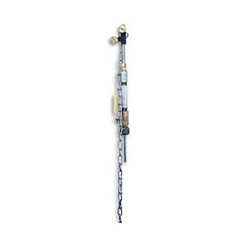
The FPT-6300 averaging pitot tube is similar to the FPT-6100 in performance, but features a wet-tap assembly which permits installation and removal of the sensor in pressurized lines without process shutdown. The weld coupling is first welded into place, then the ball valve and packing are put in place. Next, a drill is used to drill out the pipe. The drill is partially withdrawn and the ball valve is closed. The drill may then be completely removed and the sensing tube partially installed in the assembly. Finally, the ball valve is opened and the sensing tube is inserted into the flowstream. The FPT-6300 is ideal for retrofits on critical flowstreams.

Complete this questionnaire to size the Pitot tube for your application.

SPECIFICATIONS
Accuracy: Up to 1% of rate (see sizing). (Accuracy stated is for use in schedule 40 pipe. If used in schedule 80 pipe, add 1% to accuracy or request special construction)
Repeatability: ±0.1% of rate
Max Temperature and Pressure: 88°C(190°F) at 150 psig operating; 88°C(190°F) at 100 psig during insertion/removal
Unrecoverable Pressure Drop (inches H2O): = DP x (CP/D)
    where: DP = generated differential pressure (inches H2O)
    CP = pressure loss coefficient
    = 0.296 for 38" diameter probe
    = 0.387 for ½"
    = 0.757 for ¾"
    = 0.945 for 1"
    D = inside pipe diameter (inches)
Wetted Parts: carbon steel weld coupling and pipe fittings, brass ball valve and packing, and Zytel ferrule. For 316 SS construction, consult Flow Engineering Dept.

Sizing Equations
1. Any Liquid: ΔP (inH2O) = Q2(GPM) x Sf / K2 x D41 x 32.14
2. Steam or Any Gas (steam requires min ΔP of 10" H2O): ΔP (in. H2O) = Q2(lb/hr) / K2 x D41 x ρ x 128,900
3. Any Gas: ΔP (inH2O)= Q2 (scfm) x SS x (T + 460) / K2 x D41 x P x 16,590

Where:
ΔP = differential pressure (in inches H2O)
Q = flowrate
K = flow coefficient (see "how to order")
D1 = inside diameter of line size (in inches for square and rectangular ducts use): D1 = √(4 x height x width / Π)
P = static line pressure (psia)
T = temperature (in °F)
ρ = density of medium (in pounds per cubic foot)
Sf = Sp. Gr. at flowing conditions
Ss = Sp. Gr. at 15°C (60°F)

NOTE: Use of these equations for liquids yields an accuracy of ±2% of rate. When used for steam, accuracy is ±10% of rate (when steam tables are used). Gas equation yields ±2% of rate accuracy from 21 to 204°C (70 to 400°F) and 0 to 150 psig (when gas is not near its critical point). A ±1% of rate accuracy requires the use of more precise equations which account for shift in K with change in flowrate, gas compressibility, etc. Request a precision flow calibration sheet and please supply the following data: name of fluid, specific gravity, pressure, temperature, inside pipe diameter, viscosity, steam quality, degrees superheat, and ratio of specific heat at constant pressure to that at constant volume (for gas velocities approaching 500 fps).
Tous les Montants indiqués Dans EUR
Notez: Comes complete with operator's manual.
 
We noticed you are from the US. Visit your local site for regional offers and live support.